
Configure Server traffic interfaces
| Introduction |
The ByteBlower server can be configured with multiple switches and switch types yielding a flexible testing solution. This article will look at the different interfaces and daisy-chaining possibilities.
|
| Network interfaces | The ByteBlower GUI and API offer two types of network interfaces for traffic generation ("traffic interfaces"):
Since ByteBlower Server v2.14 individual trunking interfaces can be grouped together very flexibly. The examples below show some of the possibilities. Much more is possible of course! Contact us through support.byteblower@excentis.com to convert your system to a new layout. |
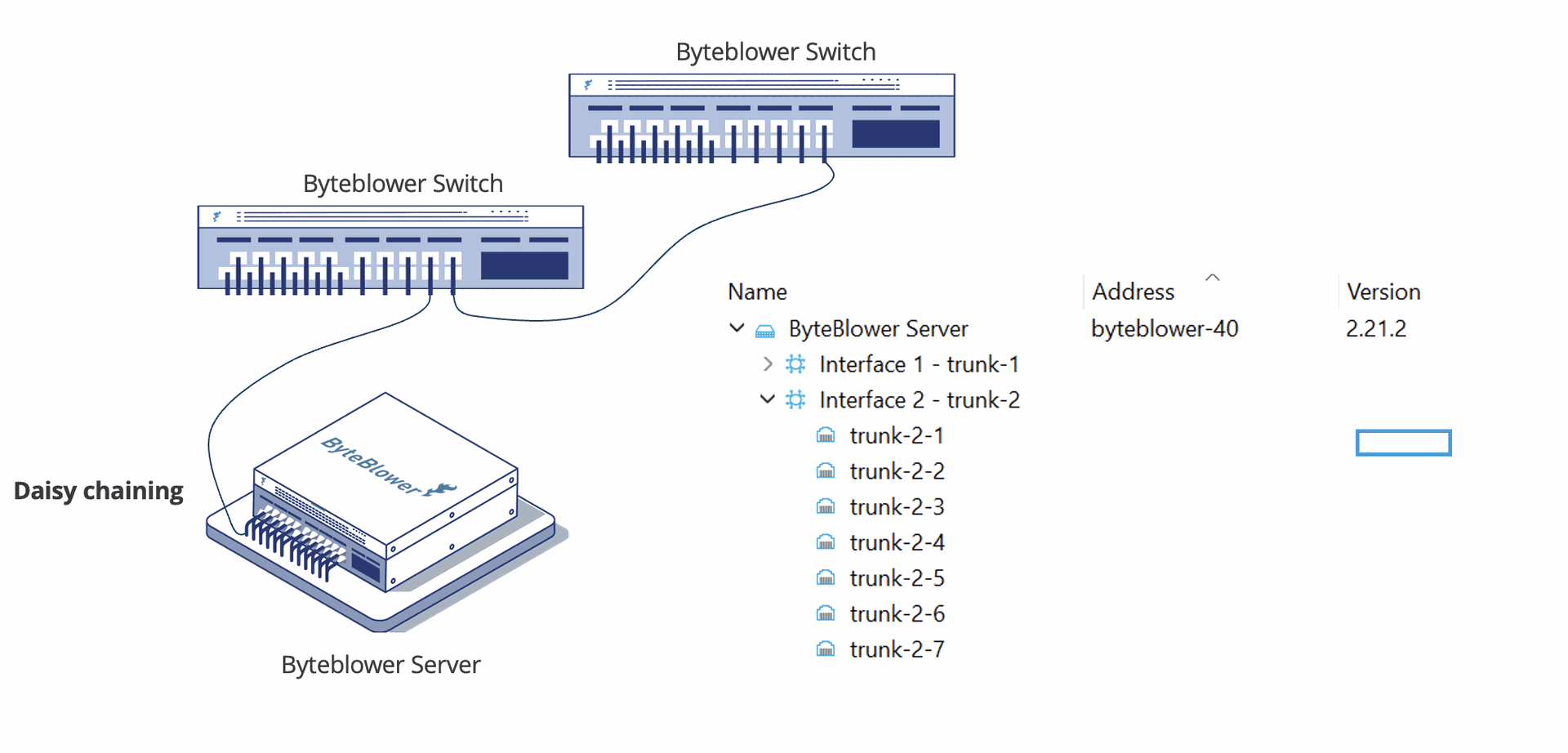
| Daisy chaining | Within ByteBlower, a daisy-chain is any setup where several switches are connected in series starting from a single ByteBlower server connector. The most common variant is where a 1Gbit switch is extended with a smaller NBASE-T capable switch (setup pages).
For older ByteBlower versions, all daisy-chained switches were grouped together in a single large trunk. As a user, you were required to perform the arithmetic where each interface was located. In the new version this has become much easier, the interfaces of each switch can easily be placed together in the same trunk. |
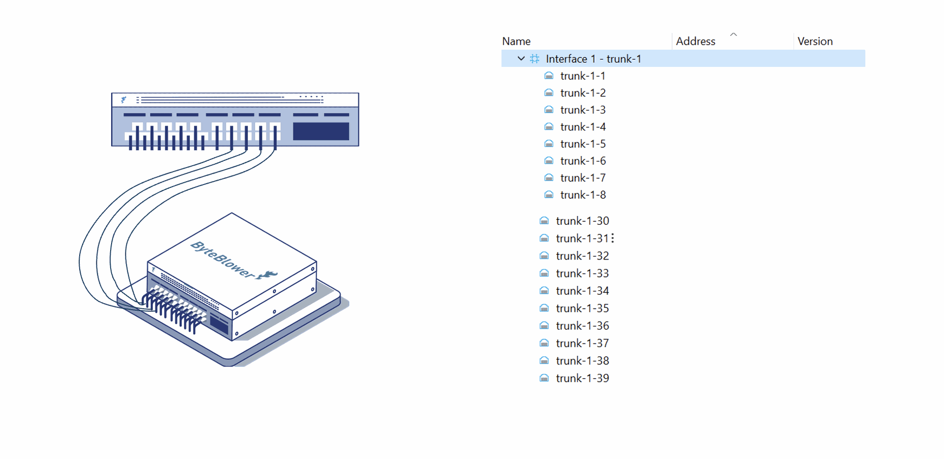
| Multi-trunk | This setup is in many ways the reverse of the above: multiple connectors on the server chassis are connected to the same switch for larger total throughput.
Prior to v2.14, the above setup resulted in 4 different trunks, with the interfaces split evenly across them. Users thus needed to calculate, themselves, where each interface was located. The new version makes it easier. All interfaces belonging to the same switch can just be grouped together in a single trunk. |
| More possibilities | The above two examples show just the 2 most common options. What else is possible?
The possibilities are limitless. Don’t hesitate to contact us if you don’t see your use case mentioned. Together we’ll make it work! |