Dealing with NAT

Introduction

This article describes the behavior of the NATDiscovery in the ByteBlower GUI. The text intends to answer technical questions. For a step-by-step guide on how to use NATDiscovery, we have an article in the examples section 📄 Use cases and examples.
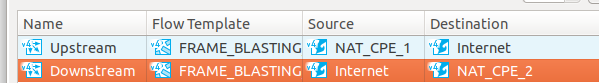
The NAT discovery is enabled in the port view. We'll assume that the reader is already somewhat familiar with how a NAT operates. The focus of this article is solely on using such ByteBlower ports for FrameBlasting.

Problem description

Any ByteBlower Port can be used as the source or destination of a FrameBlasting flow. As we'll see further, this makes an important difference. For clarity, we'll call traffic out of the NAT in the upstream direction. The ByteBlower Port with the NAT config is then the source of the flow. The reverse direction, traffic streaming into the NAT is called the downstream direction. In this second case, the NAT config is found on the destination. An example is found in the figure below.


In the figure above, both NAT_CPE_1 and NAT_CPE_2 are inside the LAN. They are configured with a valid IPv4 address and can reach each other using that address. Yet these addresses won't be known outside of their LAN. A router or modem provides the connection with the wider network. It will modify all traffic into and out of the LAN.

What part of the packets do change? Only where the frames are addressed to. This keeps the devices inside the LAN private.  A very common situation is that all upstream traffic shares the same IPv4 source address. When needed the Layer 4 port numbers (e.g. UDP) will also change. This packet modification is called a Network Address Translation or NAT. One such NAT mapping is made for each IPV4 address and UDP port number being sent upstream. The devices inside the NAT, themselves don't know to which values their packets will be translated to.

This upstream traffic is shown in the figure below. CPE1 and CPE2 both sent traffic upstream (green arrows). The addresses of this traffic are translated. A node in the Wide Area Network (WAN) can't tell anymore whether the lighter shade was from CPE1 or CPE2, only the router in the middle is able to.

Downstream traffic is trickier. The IPv4 addresses of the devices inside the LAN are kept secret, you can't thus reach them with these. In fact, you can only reach the devices using an already existing NAT mapping. This mapping is only created from upstream traffic. In summary, if you want to send traffic downstream, the CPE first needs to contact you upstream.

This translation has an impact on your ByteBlower. Default the ByteBlower uses both source and destination addresses to recognize to whom the traffic belongs. After translation, these values will have changed. The addresses thus need to be resolved; this will be described in the upstream discovery section. In addition, for downstream traffic, the NAT mapping needs to be initialized with upstream data first.

Upstream discovery

As presented above, the addresses of packets from the CPE to the WAN are translated by the NAT. The upstream discovery determines the values they are being translated to. This discovery is done for FrameBlasting flows with a source that has the NAT config enabled. It's performed while setting up the test.

Determining the translation is straightforward, the ByteBlower GUI takes the steps below:

  1. Create a frame with an easy-to-recognize payload. Base the addresses on the data you wish to send.
  2. Send the frame through the NAT.
  3. At the destination listen for the traffic from the previous step.
  4. Discover the translated addresses from the received traffic.

This forward discovery is done for all addresses. When multiple flows use the same frames and the same ports then the results of the forward discovery are reused. Most NAT devices will retain this translation for at least 2 minutes.

Below we'll briefly describe the steps in this discovery. This will help troubleshoot potential issues.

Step 1: Frame creation

A new frame is created based on the original frame. We'll call this the NAT Discovery Frame. It has the same values for the following fields:

  • MAC addresses
  • VLAN headers when applicable
  • IPv4 addresses taken from the ByteBlower Port config.
  • OSI Layer 4 type. For most configurations, this will be UDP.
  • Layer 4 port numbers.

The frame differs solely in the payload. This has been replaced with a small textual description and a unique token. It stays small: the frame is about 100 bytes including Ethernet overhead.

Step 2: Upstream traffic

The probing frame is sent out from the ByteBlower port with the NAT config. The frame rate is low: about 10 packets a second or at about 8 kbit/s. Traffic is generated for at most 20 seconds, but as we'll see next, most of the time the NATDiscovery finishes earlier.

Step 3 and 4: Receiving the frame

A RawBasicCapture captures all traffic. A BPF filter based on the IPv4, and Layer 3 (mostly UDP) destination addresses of the frame limits the number of captured packets. Each received packet is compared to the expected payload from step 1. This comparison is done eagerly: as soon as new frames arrive.

The source IPv4 address and the source Layer 4 port of the received frame are retained. We call these the public addresses. These values are used to count the traffic during the test-run.

Downstream discovery

In this section, we'll explain the downstream discovery. This algorithm is used when the destination of the FrameBlasting flow is behind a NAT.

As we mentioned in the introduction, downstream traffic through a NAT requires first upstream data. These first packets create the NAT mapping. Only after this step, downstream traffic is possible. This is reflected in the steps for the downstream discovery:

  1. Use the upstream discovery to create the NAT mapping and determine its values.
  2. Adapt the UDP frame to these new settings: The IPv4 and UDP destination addresses take the values of the forward learning.

Step 1 Do upstream discovery

Upstream discovery is started from the destination ByteBlower port, this is the ByteBlower port inside the NAT. This can be confusing: even though this port is configured to receive the traffic of the flow, it will transmit during initialization.

The public addresses are used in the second step.

Step 2: Adapt the Frames

The configured ByteBlower frames are modified to the learned NAT mapping. The public IPV4 address and learned Layer 4 port are used as the destination of the frame.