Traffic Interface Configuration
| Introduction | This article will detail how to configure a traffic interface on your server. |
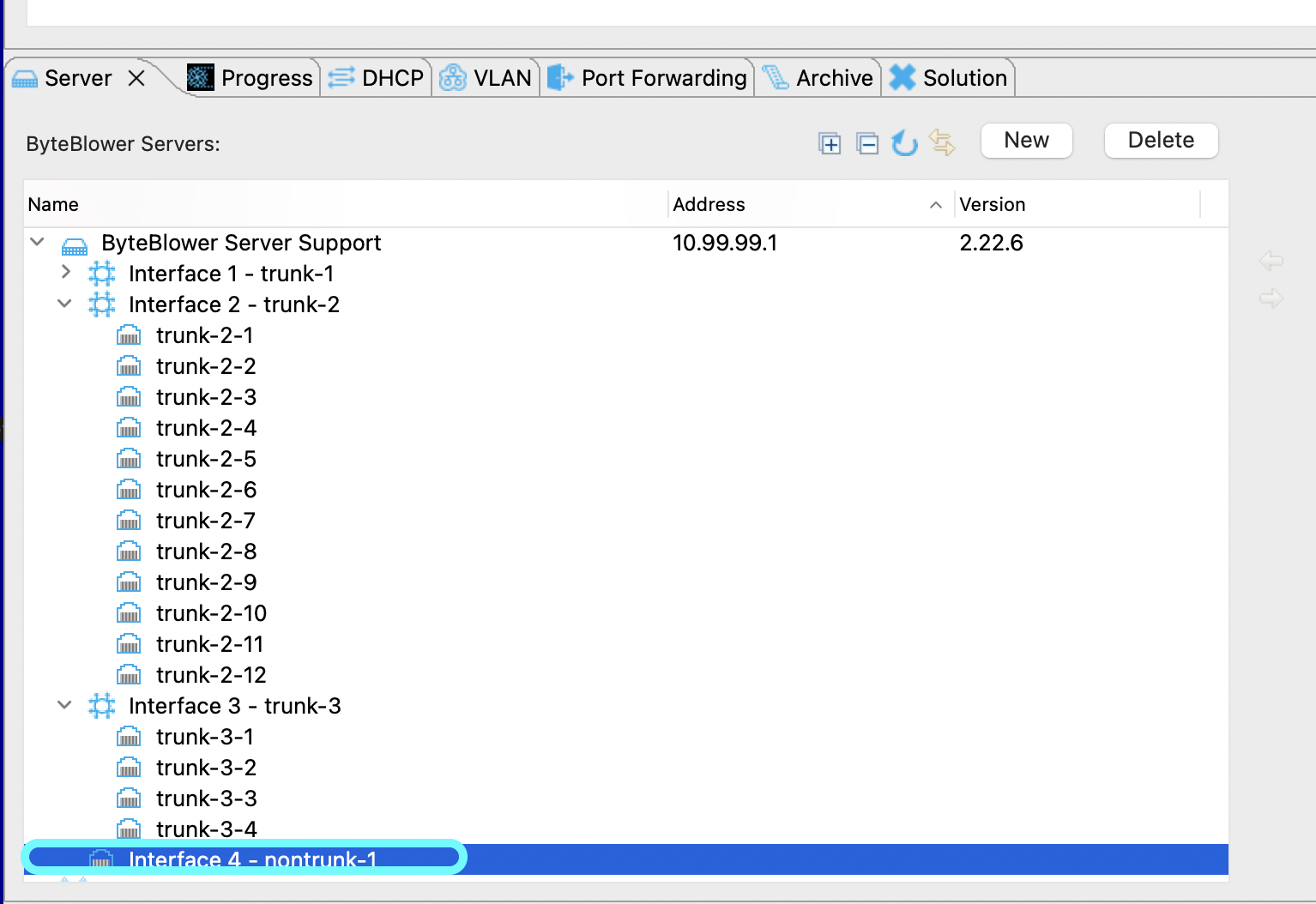
| Trunk In the GUI | The image below shows the Trunking interface on the BB GUI. Here you see that each port on the Byteblower switch has a trunking interface assigned to it. This makes it intuitive and much easier to use.
The switch above is split into multiple trunks for ease of use. The middle ports are typically assigned to Trunk-1. The 12 port extension module on the far left is assigned trunk-2. Trunk-3 is being used with a breakout cable to 4x10G ports. |
| Non-Trunk GUI | A non-trunk is typically used to connect to the backbone, NSI (CMTS) side of your network setup and is found on the Byteblower Server. However, it can be used in the same manner of a trunking interface but you will have to use VLANs to map the traffic through your network.
Non-Trunk interfaces have only one interface for docking ports. |
| Trunk to Non-Trunk | The link below will guide you through the steps to go from a Trunk Interface to a Non-Trunking Interface. Trunk to Non-Trunk |
| Non-Trunk to Trunk | The link below will guide you through the steps to go from a Non-Trunk Interface to a Trunking Interface. Non-Trunk to Trunk |
| Please Note | Important to note: your license must match the configuration applied to the Byteblower Server. It is always permissible by license to configure a Trunking interface into a Non-trunking interface. However, the amount of trunking interfaces permitted is limited by the license purchased. So if you purchased a license with one Trunk interface and one Non-Trunk interface, then you cannot have 2 Trunking interfaces. The only other combination allowed will be of 2 Non-Trunks. Also important to note is that you cannot assign a physical traffic interface on the server as both a non-trunk and a trunk at the same time. |

